
Assembly Instructions
Pre-assembly Modifications
Important: The following modifications must be completed before assembly.
Aluminum profiles
- Eight aluminum profiles (400 mm) must be drilled at both ends
- Two holes per profile (one at each extremity)
- Hole diameter: 6 mm
- Maintain a consistent distance x from the ends for all profiles
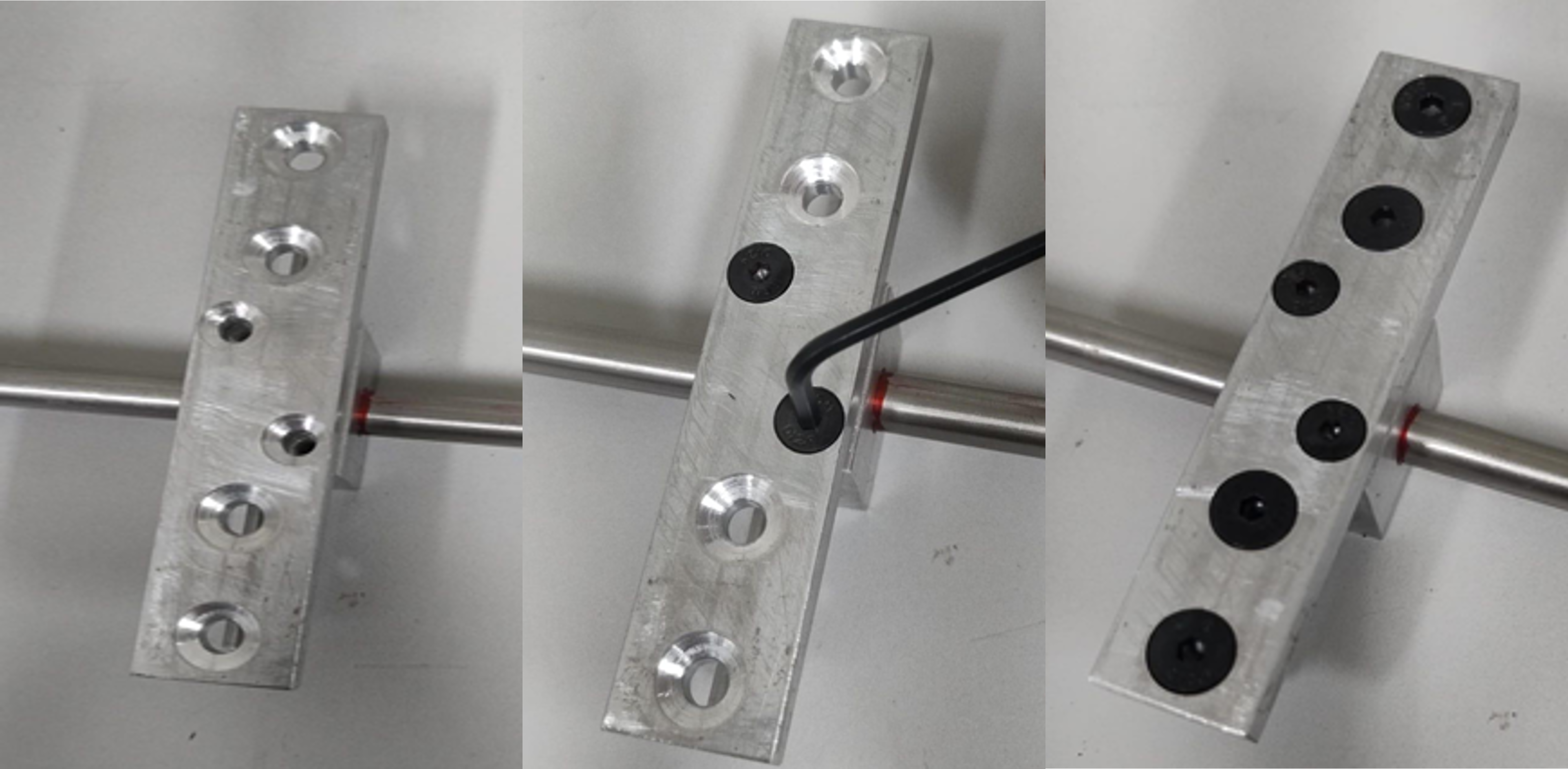
Central pillow block
- All mounting holes must be threaded for M4 screws
Part 1 — Preparation of Aluminum Profiles
Materials
- 8 × Aluminum profiles (400 mm)
- 16 × Universal connectors
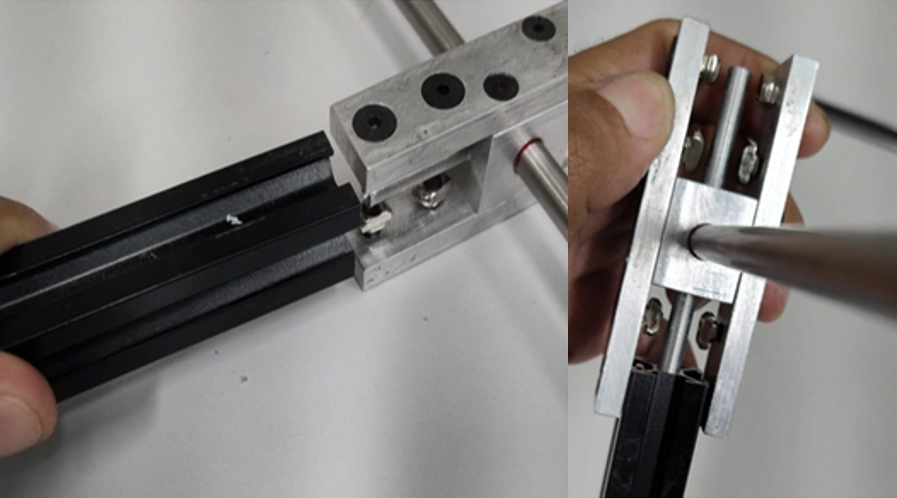
Procedure
-
Insert the connector nut into the T-slot
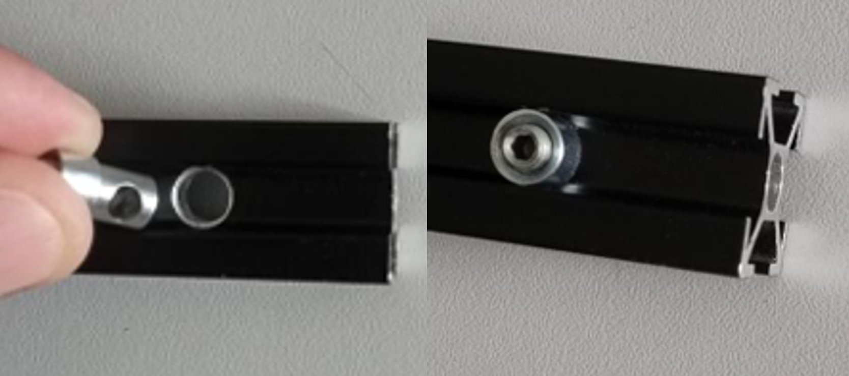
-
Insert the connector screw, keeping it perpendicular
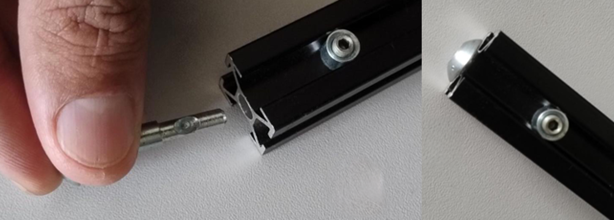
-
Tighten using an Allen key
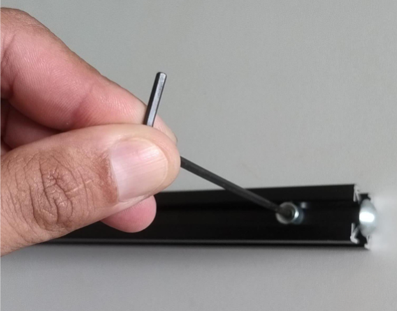
-
Repeat for the opposite end and all profiles
-
Final prepared profile:

Part 2 — Base Structure Assembly
Materials
- 4 × Aluminum profiles (500 mm)
- 8 × Aluminum profiles (400 mm)
Procedure
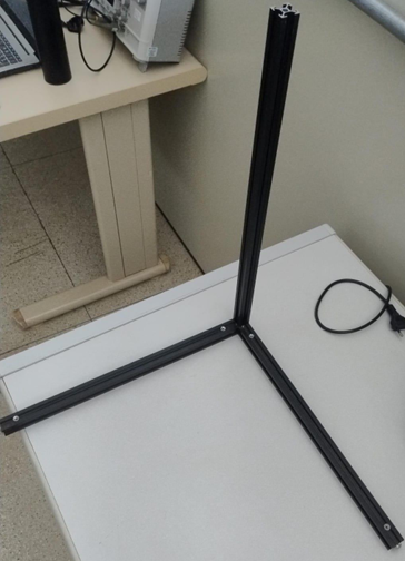
-
Arrange profiles perpendicularly
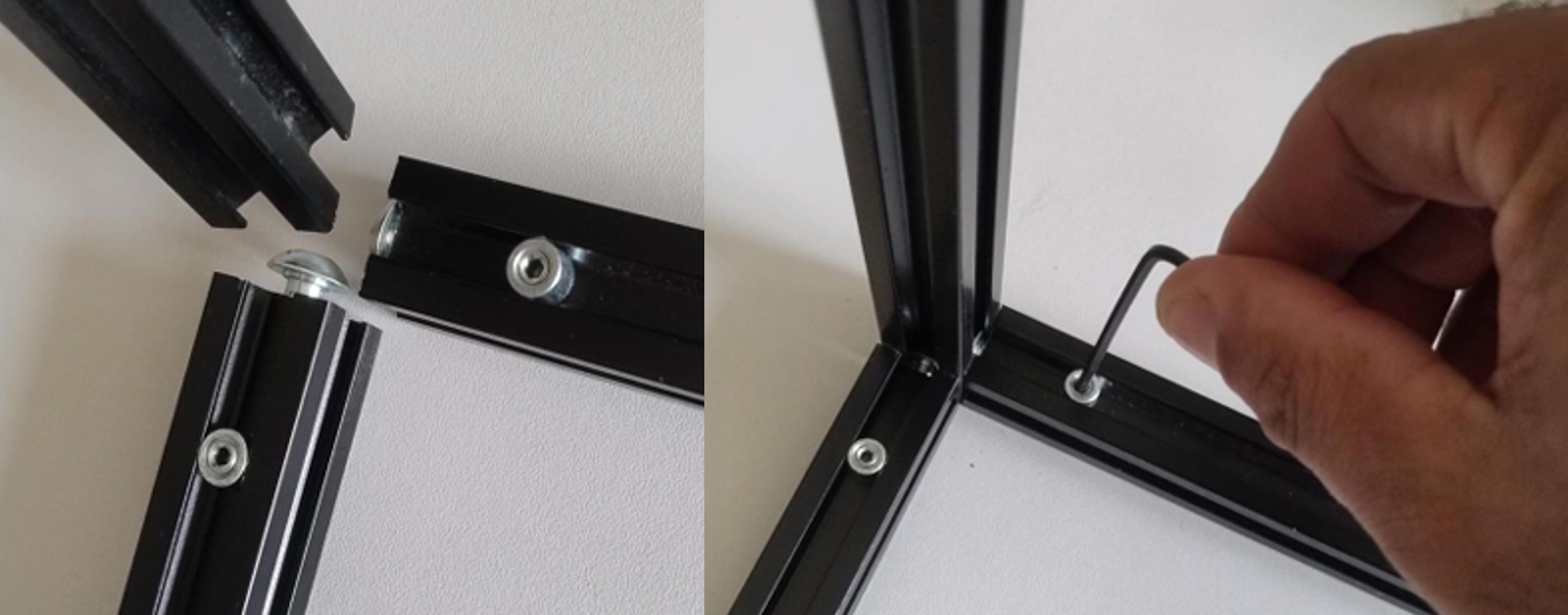
-
Tighten all connections
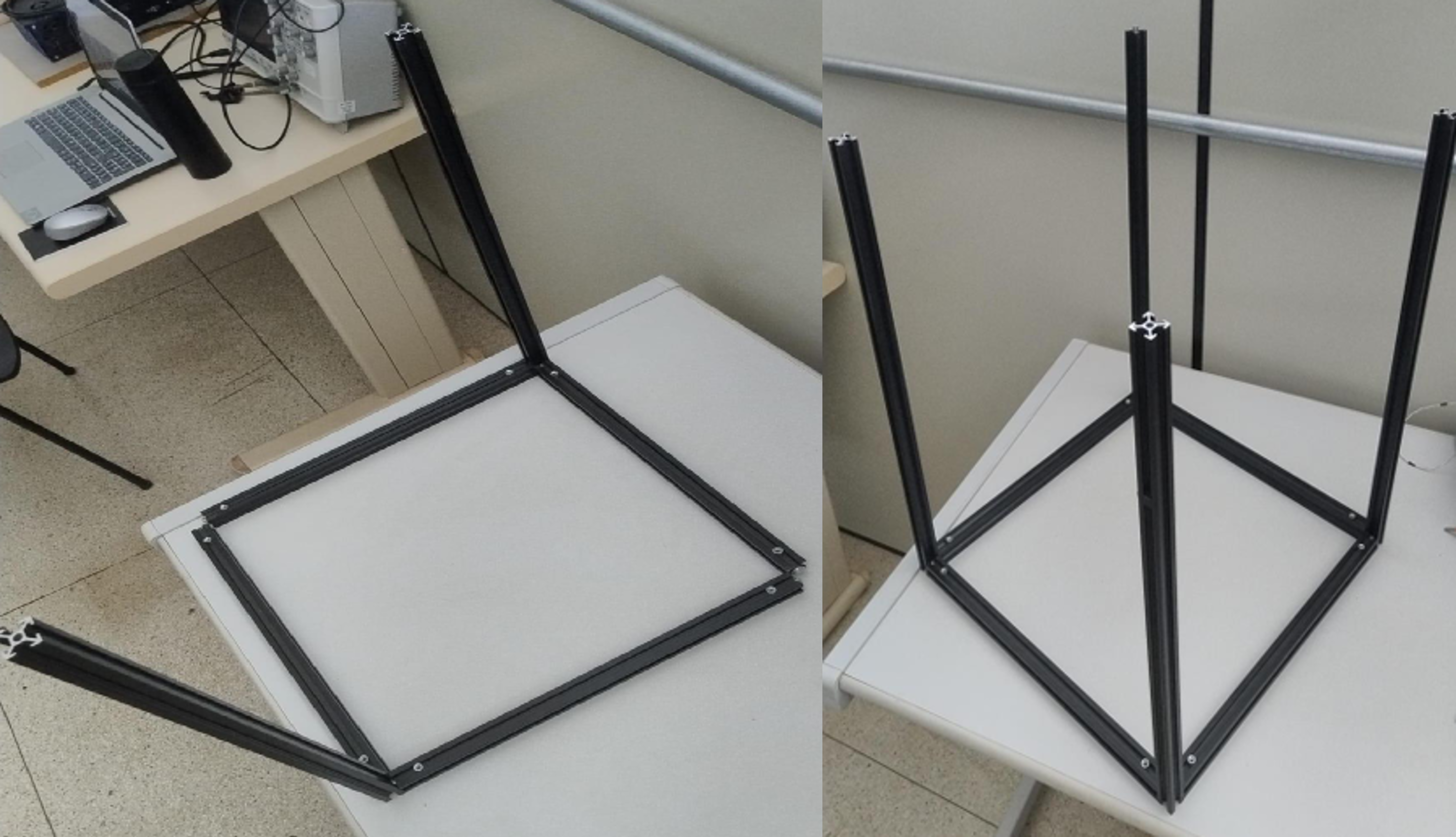
-
Assemble two identical frames
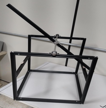
-
Join both frames into a rectangular base
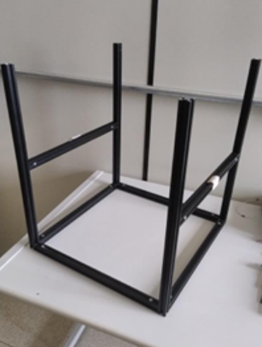
-
Fully tighten all fasteners
-
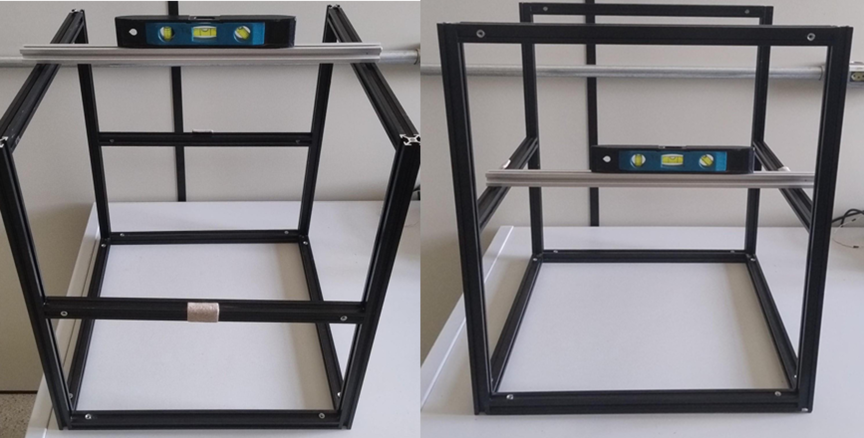
Install upper profiles as end stops (~22.5 cm height)
-
Install shaft support profiles
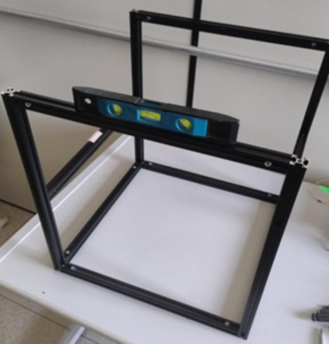
-
Verify alignment and leveling
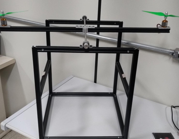
Part 3 — Rotational Axis and Actuation
Materials
- 2 × Aluminum profiles (400 mm)
- 1 × Steel shaft (8 mm × 450 mm)
- 1 × Shaft coupler
- 3 × Pillow block components
- 2 × Bearing supports
- 2 × Motor mounts
- Fasteners (M3, M4, M5 + hammer nuts)
Procedure
-
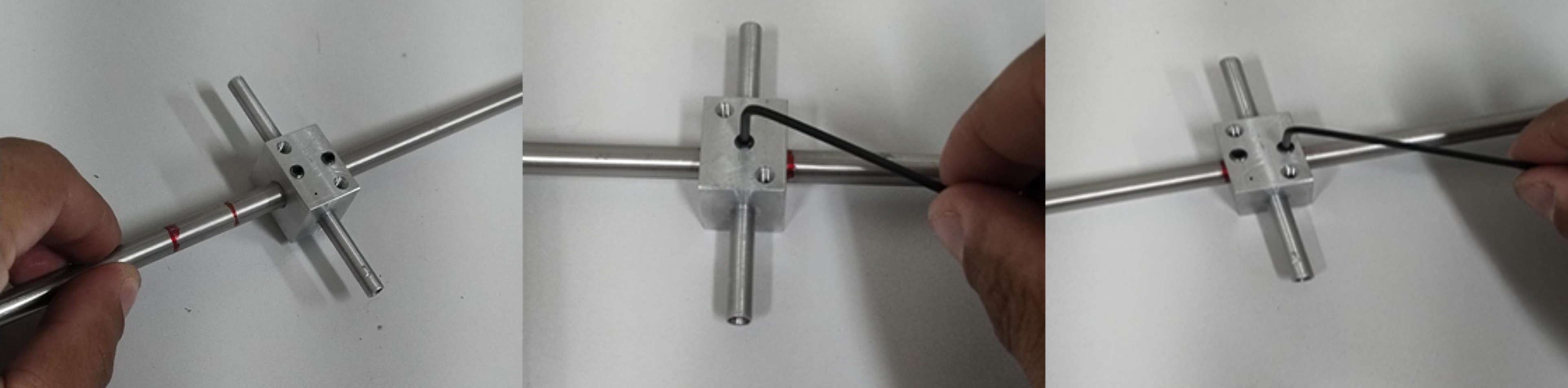
Insert shaft into central pillow block
-
Fix using M4 screws (2 top, 1 bottom)
-
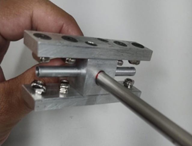
Attach locking components
-
Attach aluminum arms
-
Install bearing supports and set spacing
-
Attach shaft coupler
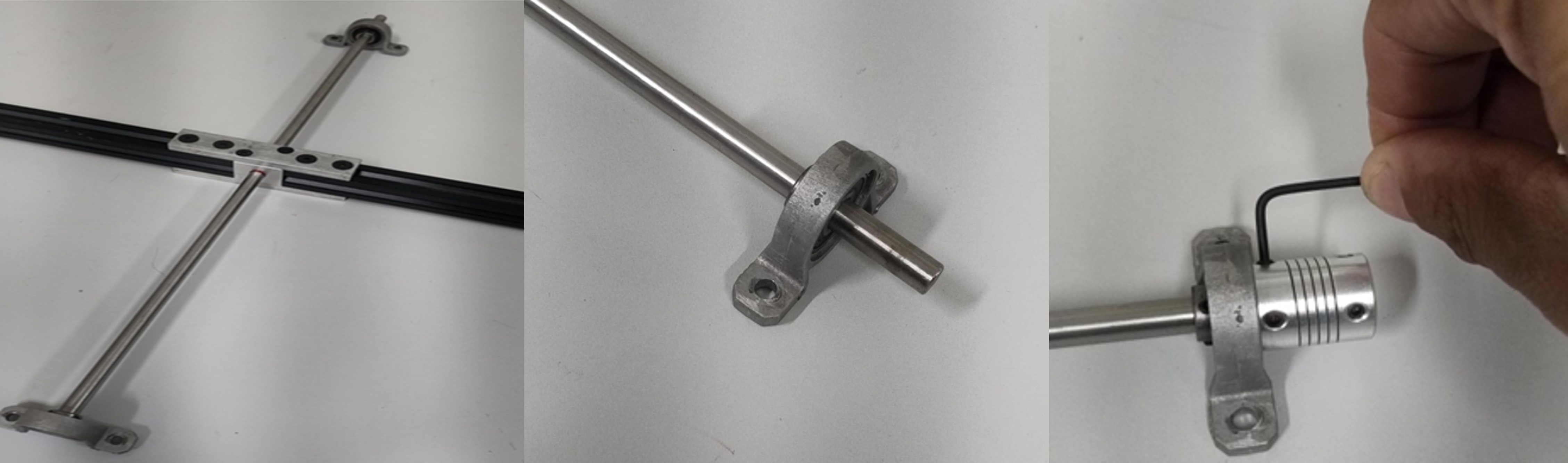
-
Fix shaft assembly to structure
-
Mount motors
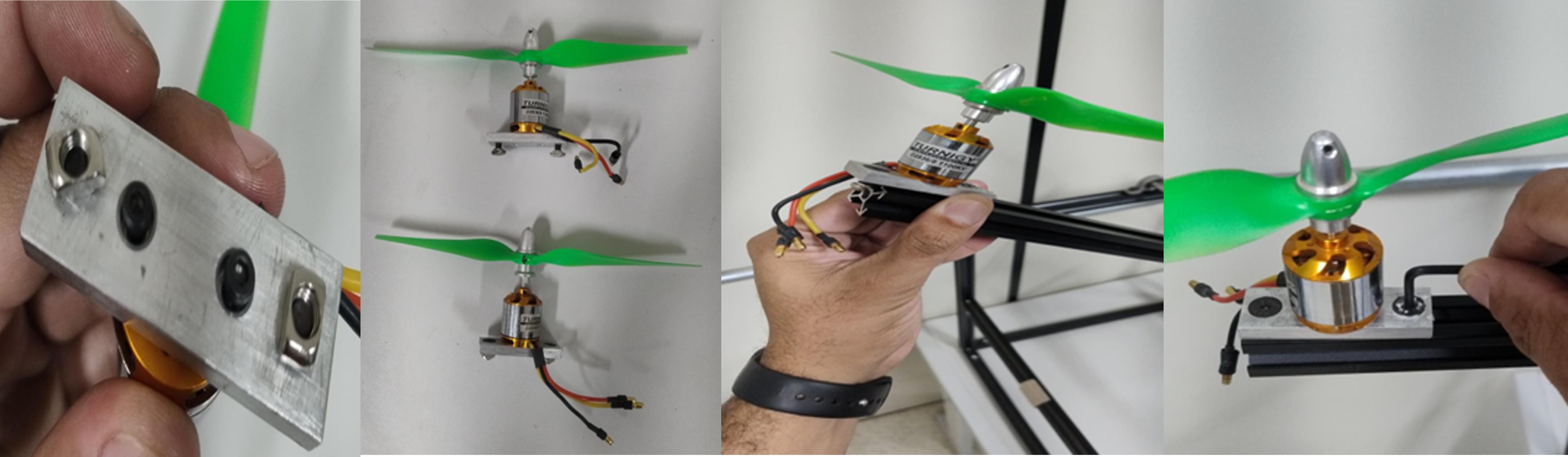
-
Attach motors to arms
Safety Notes
- Ensure all fasteners are fully tightened before operation
- Verify structural alignment before powering the system
- Keep clear of rotating propellers during testing
- Use appropriate power supply and wiring insulation